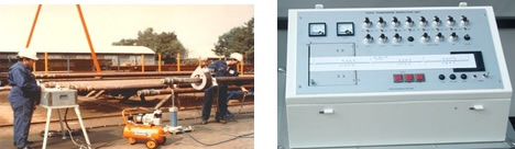
1) Visual Tube
- Full length visual examination of the inside and outside surfaces of used tubes
- Evaluating Straightness, mechanical or corrosion damage, debris such as scale or drilling mud
2) OD Gage Tube
- Full length mechanical gauging of the outside diameter of used drill pipe tubes
- Evaluating Diameter variations caused by excessive wear or mechanical damage, expansions caused by string shot, reductions caused by over pull.
|
3) UT Wall Thickness
|
 |
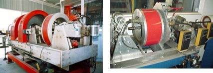
4) Electromagnetic – 1 (EMI – I)
- Full length scanning (excluding upsets) of drill pipe tube using the longitudinal field (transverse flaw) buggy type unit
- Evaluating Flaws such as fatigue cracks, corrosion pits, cuts, gouges, and other damage that exceed the specified acceptance limits
 5) Electromagnetic -2 (EMI –II)
- Full length scanning (excluding upsets) using a unit (Four function system) with longitudinal magnetic field EMI (transverse flaw), transverse magnetic field EMI (longitudinal flaw), grade verifier and Hall effect system for measuring wall thickness capabilities
- Evaluating Flaws such as fatigue cracks, corrosion pits, cuts, gouges, reduction of wall thickness, other damage that exceeds the specified acceptance limits and grade verification.
6) MPI Slip/Upset
- Examination of the external surface of drill pipe and HWDP upsets and slip areas using the active-field AC yoke dry /wet magnetic particle technique.
- Evaluating Flaws such as fatigue cracks, corrosion pits, cuts, gouges, and other damage that exceed the specified acceptance limits.
7) UT Slip/Upset
|
 |
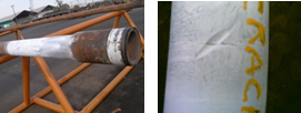
8) Visual Connection
- Visual examination of connections, shoulders, and tool joints and profile check of threads, measurement of box swell
- Evaluating Handling damage, indications of torsional damage, galling, washouts, fins, visibly non-flat shoulders, corrosion, weight/grade markings on tool joint and pin flat.
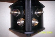
9) Dimensional – 1
- Measurement or Go-No-Go gauging of box OD, pin ID, shoulder width, and tong space
- Evaluating torsional capacity of Pin and Box, torsional matching of tool joint and tube, adequate shoulder to support makeup stresses, adequate gripping space for tongs
10) Dimensional – 2
- Dimensional – 1 requirement plus measurement or Go-No-Go gauging of pin lead, counterbore depth, box counterbore, pin flat length, bevel diameter, seal width and shoulder flatness
- Evaluating Same as dimensional – 1, plus evidence of torsional damage, potential box thread engagement with pin flat, excessive
shoulder width, sufficient seal area to avoid galling,
non-flat shoulders.
|
11) Black light Connection
|
 |